
22. 3. 2026
Protection of water pipelines against hydraulic surges: autonomous CLA‑VAL diaphragm valves as the solution
Hydraulic surges in water transmission mains are complex and often underestimated operational phenomena. They occur during changes in pumping regimes, sudden pump shutdowns, power outages or other non‑standard operating conditions. The result can be significant pressure peaks that place stress on pipelines, valves and the installed technologies themselves. At our WATER division, we have been addressing this issue for many years, and when designing solutions, we always base our approach on the specific operating conditions of the given water supply system.
One proven method of protection is the use of CLA‑VAL diaphragm control valves, which we install and set up specifically for individual applications. Their use depends on whether the system is pumping‑based or gravity‑driven, on the length and characteristics of the discharge pipeline, the connection to the distribution network, and on the possibility of utilising overpressure or backpressure from a storage reservoir or another pressure source. These factors are decisive in determining whether an active or passive surge protection approach is appropriate, or whether a combination with other conventional solutions, such as air vessels, should be applied.
Active surge protection operates as an autonomous hydraulic device that is independent of electrical power and operator intervention. The valve is typically installed on a branch from the discharge pipeline and, when a pressure peak occurs, it is able to divert excess water back within a very short time – for example to the pump suction header or into a storage reservoir. This solution is often applied in cases where the original surge vessels are no longer functional or where changes have been made to the pumping technology. As the valve remains inactive for most of the time, it must also be designed with long‑term reliability and resistance to incrustation in mind.
Diagram of active surge protection:
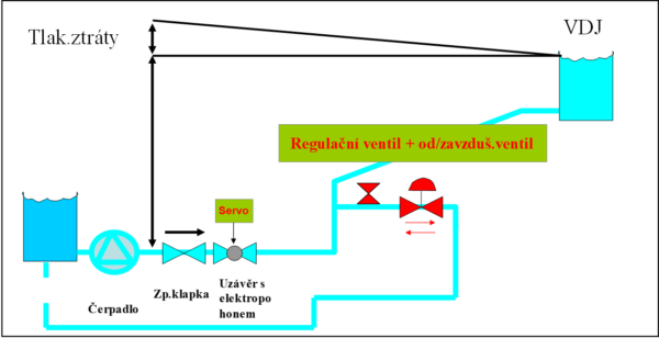
The disadvantages of this approach include the following:
- Limited valve response speed – depending on the length of the discharge pipeline and the propagation speed of the surge wave.
- Low pumping head (H) – resulting in a risk of sub‑atmospheric pressure conditions, which cannot be addressed by a control valve alone.
- Disposal of larger volumes of water during an active surge event – the question of where the excess water can be safely discharged.
Possible installation of a control valve – illustration:
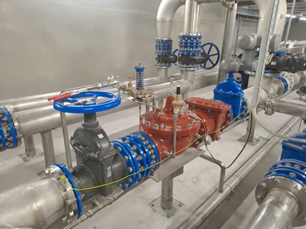
The image is from the VDJ Lesná facility of Brněnské vodárny a kanalizace, a.s.
Passive surge protection, by contrast, operates continuously in direct relation to pump operation. The control valve is installed immediately downstream of each pump, and its function is to smoothly regulate the flow during both pump start‑up and shutdown. In this way, pressure surges are suppressed directly at their source. This type of protection has proven highly effective in practice, primarily because the valve operates during every operating cycle, ensuring a stable water network free of pressure peaks. In some applications, the valve can even replace several conventional fittings, resulting in space savings and a significant reduction in pressure losses.
Schematic diagram of passive surge protection:
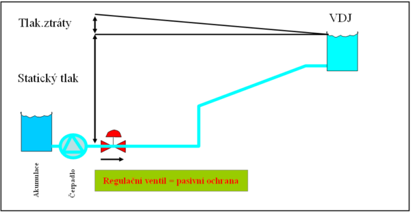
The disadvantages of this solution include the following:
- If the pump is equipped with a variable frequency drive (VFD), the valve opening mode must be adjusted – the opening and closing of the valve need to be stepped or staged so that the valve response corresponds to the characteristics of the VFD.
- It is recommended to install a control valve on the discharge line downstream of each pump in order to reduce pressure losses. Installing a single valve on a common discharge line downstream of multiple pumps is not a hydraulically optimal solution.
Possible installation of a control valve – illustration:
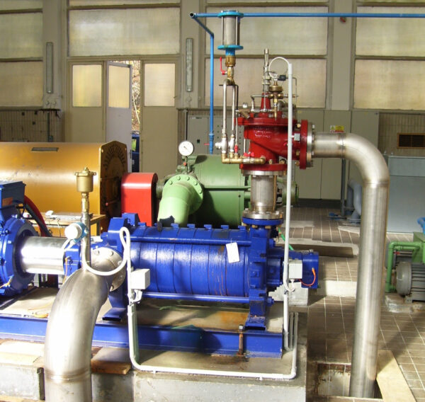
Středočeské vodárny, a.s. – UV Klíčava (corner configuration)
When designing a solution, it is also important to distinguish the characteristics of the surge wave. For shorter discharge pipelines, where rapid pressure changes occur including sub‑atmospheric phases, the use of a surge vessel or a combination of a surge vessel and a control valve is often appropriate. In such cases, the CLA‑VAL valve provides a fast response to the overpressure phase of the surge wave and helps keep system pressure within safe limits, often with a requirement for full valve opening within a matter of seconds.
Based on our experience from implemented projects, CLA‑VAL diaphragm control valves are widely applied at pumping stations, water transmission mains and at inflows to storage reservoirs, where surge protection can remain active even when the reservoir is full and the control valve is in the closed position. Every surge protection solution must be based on a thorough assessment of the specific system and its individual operating states. For this reason, we have expanded our activities to include mathematical modelling, enabling us to offer not only a high‑quality control valve but also a comprehensive surge protection concept for the entire water system. This individual approach is considered essential at HUTIRA.
If you are dealing with recurring pressure peaks, failures, or are looking for a systematic way to stabilise the operation of a water pipeline, CLA‑VAL valves represent a solution with which we have long‑term, proven experience. We will be pleased to analyse your specific case and propose a technical solution that is fully functional and robust under real operating conditions.